Restoring a Classic Spectrum Analyzer Part 5 - Final Installation
12/04/13 10:52
It is a very gratifying experience to see the transformation of this spectrum analyzer from a dusty well-used instrument into a clean and shiny example of HP’s finest engineering. I must admit that I do enjoy the process of restoring test instruments into almost-new condition. These restoration efforts are not just cosmetic, but also functional and hopefully within specification. Luckily, most of my instruments have worked perfectly upon arrival. Only in some cases, such as the Giga-Tronics GT9000 RF synthesizer and the Advantest R3765B vector network analyzer have I actually been required to diagnose and repair the instrument. Fortunately in both cases the repairs were relatively minor and both instruments have been useful laboratory workhorses.
This underscores an important point about the modestly low risk of servicing a used instrument of this vintage and earlier. Service documentation is relatively easy to find on the internet, spare modules or components are often available, and generally these instruments were engineered in a way that makes servicing, repair and calibration relatively easy. Contrast this to how test instruments are built today. Most modern instruments I’ve encountered are frequently built around a PC motherboard inside a less durable chassis with a much higher proportion of plastic components. The instrument’s functionality is mostly implemented in software running in MS Windows. When the hard disk crashes, so does your instrument. It is frustrating to turn on an instrument and wait several minutes for it boot Windows; even more frustrating when a measurement is interrupted by a software crash or an annoying OS notification window. I prefer embedded software written to a non-volatile solid state storage device as was the case with older instruments. They start up/boot very quickly and are not vulnerable to the limited life span of a hard disk or the weakness of a consumer operating system.
Now that I’ve made my point on serviceability and reliability, its time to return the spectrum analyzer! All of the MMS modules were installed according to the slot configuration I described in Part 2 of this article series. By this time, the blank filler panels and HP rack ears had arrived and were also ready for installation. Before wiring all of the rear panel interconnect cables, I installed the instrument into the rack. That way I could use the rack hardware and structure to help with cable management, i.e. using the rear rack rails to secure cable ties and velcro strips.
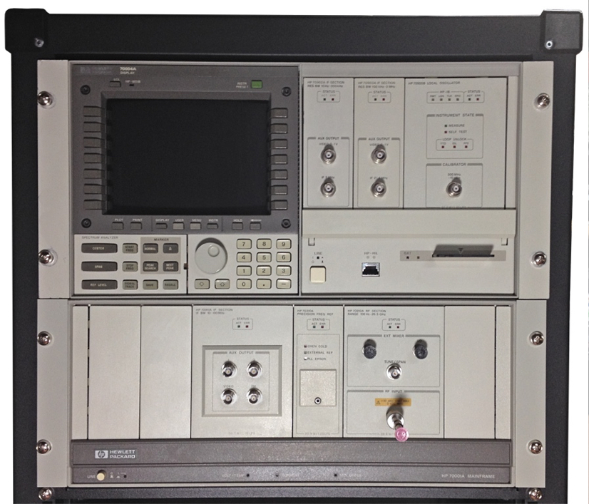
The illustration below shows the spectrum analyzer mounted into the rack with its filler panels and rack ears installed. Also note the addition of the 70903A IF Section module between the 70902A and 70900B. It arrived during the restoration process and was also treated to the same refurbishment as the other MMS modules.
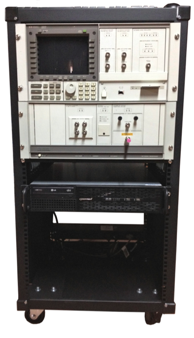
This illustration shows the entire rack with the laboratory PC mounted below the spectrum analyzer:
The interconnecting coaxial cables between MMS modules were installed. Many of the cables that came with the instrument were substituted with new cables mainly because of the additional length required due to the new module configuration. Cables were loosely bundled with velcro strips to prevent snagging and to keep the rear of the instrument relatively clear. AC power cables were installed and tucked neatly behind the rack rail down to the rack mount power-bar/surge suppressor.
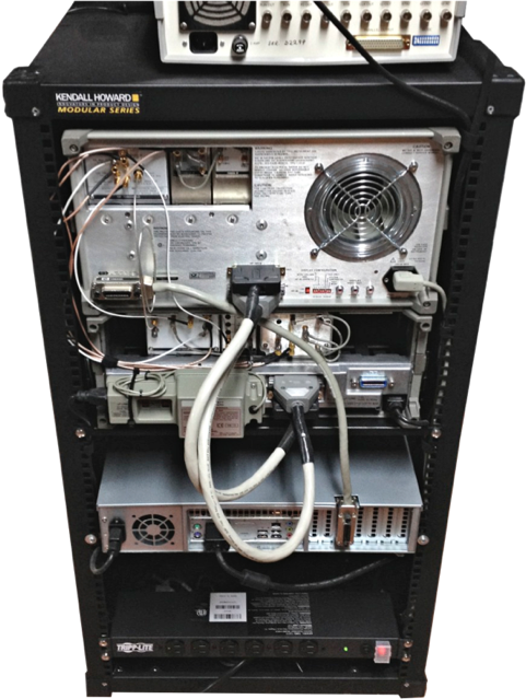
The illustration above also shows the crude home-made MSIB cables that came with the instrument. They are somewhat of a nuisance since they jut out from the rear of the rack and often interfer with nearby objects when the rack is repositioned. The multi-core cable that was used to make these cables is quite rigid and does not consist of bundles of twisted pairs. I believe the original MSIB cables from HP were made with twisted pairs for better transmission line performance. Given the short length of these cables, its impedance characteristics are likely not a big factor. However, I want to replace these cables with better alternatives that are more flexible and robust. Finding a pair of HP MSIB cables is quite difficult and most of the ones I have seen for sale have been outrageously expensive. Luckily, the cable pinout is relatively well documented and some folks have made pretty good DIY cables, such as R. Barrios EB4EQA. I am going to make a cable pair myself and have already purchased the connectors and accessories to do so as shown below:
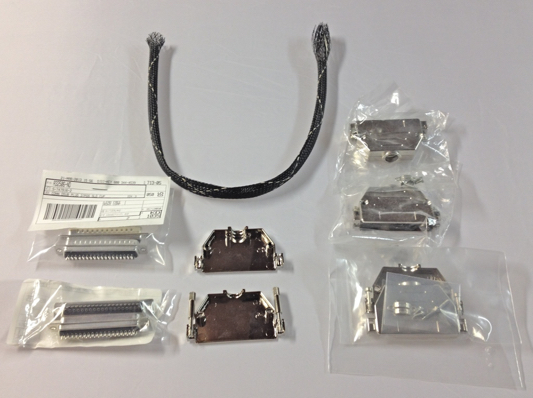
I will be able to make braided cable assemblies at an optimum length to connect both mainframes with minimal protrusion beyond the rack footprint.
In conclusion, this has been a rewarding and enjoyable project. My laboratory now has a pristine high-performance spectrum analyzer which is actively used and provides invaluable measurement capabilities. Its dedicated GPIB connection to the rack-mounted PC has been immensely useful. In particular, I have been able to use some excellent freely available software such as John Miles’ KE5FX GPIB toolkit. This toolkit includes a very useful phase noise measurement utility. This utility was invaluable for developing the ultra-low phase noise sampling clocks used in the D770x digitizer products for example. Also, being able to capture measurement traces directly from the instrument and on to a network file system has also been very useful. Although, adding a VGA capture device such as the Epiphan VGA2USB LR looks tempting in order to capture measurements faster. In addition, it would be nice to capture live frame rate video from the 70004A like this setup in Lambert Lake, Canada. No doubt, I will be able extend the functionality of this measurement setup in support of future applications and also have fun in the process!
This underscores an important point about the modestly low risk of servicing a used instrument of this vintage and earlier. Service documentation is relatively easy to find on the internet, spare modules or components are often available, and generally these instruments were engineered in a way that makes servicing, repair and calibration relatively easy. Contrast this to how test instruments are built today. Most modern instruments I’ve encountered are frequently built around a PC motherboard inside a less durable chassis with a much higher proportion of plastic components. The instrument’s functionality is mostly implemented in software running in MS Windows. When the hard disk crashes, so does your instrument. It is frustrating to turn on an instrument and wait several minutes for it boot Windows; even more frustrating when a measurement is interrupted by a software crash or an annoying OS notification window. I prefer embedded software written to a non-volatile solid state storage device as was the case with older instruments. They start up/boot very quickly and are not vulnerable to the limited life span of a hard disk or the weakness of a consumer operating system.
Now that I’ve made my point on serviceability and reliability, its time to return the spectrum analyzer! All of the MMS modules were installed according to the slot configuration I described in Part 2 of this article series. By this time, the blank filler panels and HP rack ears had arrived and were also ready for installation. Before wiring all of the rear panel interconnect cables, I installed the instrument into the rack. That way I could use the rack hardware and structure to help with cable management, i.e. using the rear rack rails to secure cable ties and velcro strips.
The illustration below shows the spectrum analyzer mounted into the rack with its filler panels and rack ears installed. Also note the addition of the 70903A IF Section module between the 70902A and 70900B. It arrived during the restoration process and was also treated to the same refurbishment as the other MMS modules.
This illustration shows the entire rack with the laboratory PC mounted below the spectrum analyzer:
The interconnecting coaxial cables between MMS modules were installed. Many of the cables that came with the instrument were substituted with new cables mainly because of the additional length required due to the new module configuration. Cables were loosely bundled with velcro strips to prevent snagging and to keep the rear of the instrument relatively clear. AC power cables were installed and tucked neatly behind the rack rail down to the rack mount power-bar/surge suppressor.
The illustration above also shows the crude home-made MSIB cables that came with the instrument. They are somewhat of a nuisance since they jut out from the rear of the rack and often interfer with nearby objects when the rack is repositioned. The multi-core cable that was used to make these cables is quite rigid and does not consist of bundles of twisted pairs. I believe the original MSIB cables from HP were made with twisted pairs for better transmission line performance. Given the short length of these cables, its impedance characteristics are likely not a big factor. However, I want to replace these cables with better alternatives that are more flexible and robust. Finding a pair of HP MSIB cables is quite difficult and most of the ones I have seen for sale have been outrageously expensive. Luckily, the cable pinout is relatively well documented and some folks have made pretty good DIY cables, such as R. Barrios EB4EQA. I am going to make a cable pair myself and have already purchased the connectors and accessories to do so as shown below:
I will be able to make braided cable assemblies at an optimum length to connect both mainframes with minimal protrusion beyond the rack footprint.
In conclusion, this has been a rewarding and enjoyable project. My laboratory now has a pristine high-performance spectrum analyzer which is actively used and provides invaluable measurement capabilities. Its dedicated GPIB connection to the rack-mounted PC has been immensely useful. In particular, I have been able to use some excellent freely available software such as John Miles’ KE5FX GPIB toolkit. This toolkit includes a very useful phase noise measurement utility. This utility was invaluable for developing the ultra-low phase noise sampling clocks used in the D770x digitizer products for example. Also, being able to capture measurement traces directly from the instrument and on to a network file system has also been very useful. Although, adding a VGA capture device such as the Epiphan VGA2USB LR looks tempting in order to capture measurements faster. In addition, it would be nice to capture live frame rate video from the 70004A like this setup in Lambert Lake, Canada. No doubt, I will be able extend the functionality of this measurement setup in support of future applications and also have fun in the process!